|
Purpose:
With this tool you can create closed polylines from a selection of lines, arcs and/or polylines. This is useful if, for example, you have a parcel subdivision drawn with lines and arcs and you need to create a closed polyline for each subdivision to be able to link properties to spreadsheet cells such as polyline area or vertex coordinates. Instead of drawing each polyline manually with AutoCAD commands, this tool creates them automatically for you. It is much faster than using the AutoCAD BPOLY command and is fully automatic. Tolerance gap distances and minimum area parameters can be specified to detect closed regions even if the entities don't intersect properly.
Internal polylines are polylines created from every valid region detected. External polylines are polylines that wrap groups of valid regions.
Related web videos:
.png) See the Global Boundary Generator Video (4:00 min) for more detailed information about this command. See the Global Boundary Generator Video (4:00 min) for more detailed information about this command.
|
.png)
Fig. 1: Internal closed polylines from selected lines and arcs.
|
.png)
Fig. 2: External closed polylines (thick line) from selected lines and arcs.
|
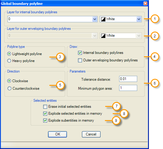
1. Layer for internal boundary polylines. An existing layer can be selected from the list or a new layer name can be typed and the corresponding color selected.
2. Layer for external boundary polylines. An existing layer can be selected from the list or a new layer name can be typed and the corresponding color selected.
3. Polyline type. Polylines can be generated as normal light weight polylines or as heavy polylines.
4. Draw internal/outer enveloping boundary polylines. Internal polyline (one polyline for every valid region detected) or external polyline (wraps groups of valid regions, see fig. 1 and 2)
5. Direction. This option is used to process polygon vertices in clockwise or counterclockwise direction.
6. Parameters. Tolerance distance to consider if two entities intersect even if they do not touch each other. Regions that have an area less than the minimum will not be processed.
7. Erase initial selected entities. If this options is checked the original selected set of lines, arcs, circles and/or polylines will be deleted, leaving only the closed polylines created.
8. Explode selected entities in memory. Check to explode selected entities like blocks, hatches or custom objects. The resulting lines, arcs and circles will be processed to draw closed polylines. Original entities will not be affected.
9. Explode subentities in memory. Selected entities will be recursively exploded until the resulting subentities are valid lines, arcs or circles. For example, if block inserts are selected they will be exploded until all valid lines, arcs and circles are found. Original entities will not be affected.
Tip: If you need to save information in each polyline vertex, select the heavy polyline type generation option. Processing entity relationships is possible, for example, to save information in each polyline vertex about the closest text entity found and create a report of vertex coordinates and the corresponding text description.
|